
-
FSP101-ATLAS
 Detektor
Inner Detector
·
Detektor
Inner Detector
·
Inner DetectorThe Inner Detector (ID) is situated in a 2T solenoidal magnetic field, generated by about 10 km of superconducting cable, wound into a coil at the inner surface of the calorimeter cryostat. The outer wall of the cryostat acts as a return yoke for the magnetic field. The coil, weighing about 4 tons, iscooled to 4.5 K by liquid helium. The Inner Detector is contained within a cylinder of about 7m length and 1.15m radius. Pattern recognition, momentum and vertex measurements,and enhanced electron identification are achieved through a combination of high-resolution pixel and strip (SCT) detectors in the inner part and continuous straw-tube tracking detectors with transition radiation capability (TRT) in the outer part of the tracking volume. 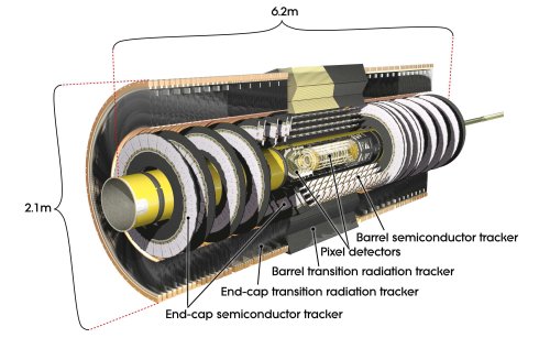
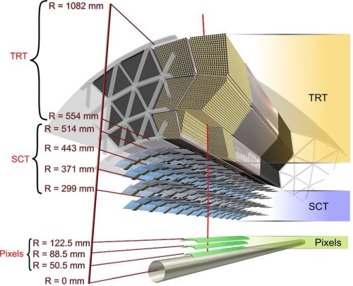
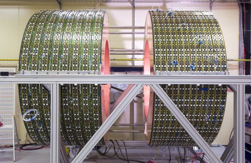
Pixel DetectorThe ATLAS Pixel Detector provides a very high granularity, high precision set of measurements as close to the interaction point as possible. The system provides three precision measurements over the full acceptance, and mostly determines the impact parameter resolution and the ability of the Inner Detector to find short lived particles such as B-Hadrons. The system consists of three barrels at average radii of ~ 5 cm, 9 cm, and 12 cm (1456 modules), and three disks on each side, between radii of 9 and 15 cm (288 modules). Each module is 62.4 mm long and 21.4 mm wide, with 46080 pixel elements read out by 16 chips, each serving an array of 18 by 160 pixels. The 80 million pixels cover an area of 1.7 m2. The readout chips must withstand over 300 kGy of ionising radiation and over 5x10¹⁴ neutrons per cm2 over ten years of operation. The modules are overlapped on the support structure to give hermetic coverage. The thickness of each layer is expected to be about 2.5% of a radiation length at normal incidence. Typically three pixel layers are crossed by each track. The pixel detector can be installed independently of the other components of the inner detector. In the starting phase, only two of the three layers planned for will be installed. Semiconductor Tracker (SCT)The microstrip detector forms the middle layer of the Inner Detector. It consists of 4 concentric barrel layers and two end-caps of nine disks each. The barrel layers carry 2112 detector modules, while 1976 endcapmodules are mounted on the disks. The whole SCT occupies a cylinder of 5.6 m in length and 56 cm in radius with the innermost layer at a radius of 27 cm. Its geometry is designed in a way that the SCT on average provides four precision space-points per track up to a pseudorapidity of |η| ≤ 2.5. The silicon modules consist of one or two pairs of single-sided p-in-n microstrip sensors glued back-to-back at a 40 mrad stereo angle to provide two-dimensional hit information. The 285 μm thick sensors are divided into 768 AC-coupled strips with an active length of 123.2 mm and a pitch of 80 μm for the barrel modules and 57 - 94 μm for the wedge shaped end-cap modules. The sensor pairs are mounted on a thermally highly conductive carbon base board that provides cooling. The SCT sensors are operated at -7◦C to prevent reverse annealing of radiation damage. Modules in the barrel part are all identical while the end-cap modules come in four different geometries, depending on their radial position on the disks.The detector has an active area of 61 m2 of silicon detectors, with 6.2 million readout channels. The spatial resolution is 16 μm in Rφ and 580 μm in z direction. Tracks can be distinguished if separated by more than ∼ 200μ m. The signals from the sensors are read out by binary front-end electronics,data is converted into optical signals directly on the module. One incoming optical link is used for configuration and triggering whiledata is transmitted via two outgoing links. One driver is sufficient for data transmission, thus ensuring redundancy and failure safety. The off-detector electronics is similar to that used in the pixel detector. 
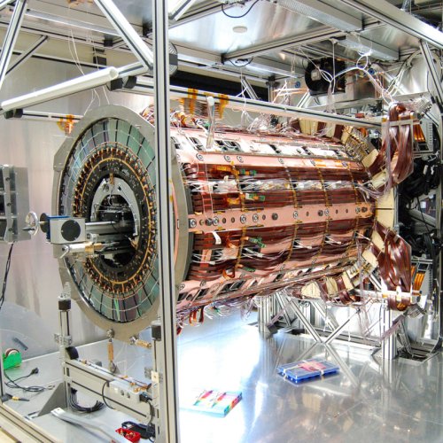
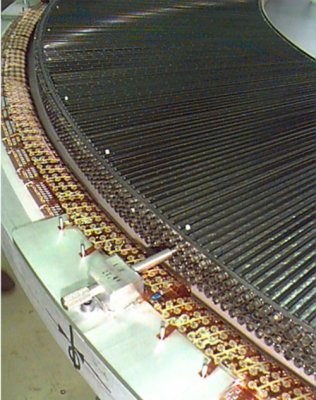
Transition Radiation Tracker (TRT)The TRT is the outermost part of the Inner Detector. It provides charged-particle tracking, using 420 000 readout channels, as well as electron identification through transition radiation measurements.The TRT consists of a central barrel and three end-caps on either side, referred to as end-caps A,B and C with the installation of the end-caps C being postponed. With this geometry the TRT delivers 36 hit measurements on average up to |η| ≤ 2.1.Straw drift-tubes are used for tracking. The straws have a diameter of 4 mm and a length of 39 cm in the end-caps A and B, and a length of 144 cm in the barrel. They are operated in proportional mode in a gas mixture of 70% Xe, 27% CO2 and 3% O2,with an avalanche gain of 2.5 × 10⁴. The sense wires are 30 μm in diameter, gold-plated tungsten wires. The straw wall is held at a voltage of -1530 V with respect to the sense wire. A single-point resolution of 170 μm in rφ direction can be achieved. Particle identification is done by efficiently converting the transition radiation photons, that are emitted when a charged ultra-relativistic particle crosses the interface between media with different dielectric constants ǫ. As the number of photons emitted per transition is on the order of γαem, with αem being the electro-magnetic coupling constant and γ = E/m, the number of transitions needs to be large. The energy of the emitted photons depends on the materials used as itis proportional to the squared difference of the plasma frequencies, (ω1 − ω2)2. For the TRT this is on the order of 10 keV as the materials are polypropylene (in fibers or foils to increase the number of transitions) and CO2 gas. Thus the energy deposition in the TRT isthe sum of ionization losses of charged particles (∼2 keV on average) and the larger deposition due to transition radiation photons (typically>5 keV). Two thresholds are applied to the signals from the straws. A low thresholdat about 250 eV to detect all hits, and a high threshold around 5 keV for the transition radiation hits. The high threshold is optimized to distinguish between electron and pion hits as electrons produce more high threshold hits than pions.In order to reduce occupancy in the barrel the straws are divided in two halfs that are read out separately at either end of the barrel. Toprovide a z coordinate the drift time in each straw is measured. In testbeam studies a maximum drift time of 48 ns was measured, resultingin a resolution of ∼130μm with an efficiency of ∼87% at a threshold of 250 eV. Single-straw hit efficiencies have been measured at 96%. 
|
